Today in North America, animal-drawn plows are largely of two types: the walking plow, and the sulky plow. The walking plow is the simplest, made up of a bottom, beam, and handles. The sulky plow is more complex, with the addition of a land wheel, a furrow wheel, a seat, and various controls. One plow that was very common in history is missing from our modern landscape, however: the wheeled, walk-behind plow.

Wheeled plows are quite old. You can see wheeled plows in centuries-old woodcuts and paintings. The Roman historian Pliny, writing in the first century AD, mentions that a plow with two wheels had recently been invented. Wheeled plows were common in Europe throughout the middle ages. However, the steel plow that John Deere developed in the 1830's did not have wheels, and the walking plow (without wheels) ruled supreme for much of the next century. At the same time, wheeled plows made up a substantial portion of the plows used in Europe. Even today, some European teamsters continue to use wheeled plows, most notably the two-way brabant plow.
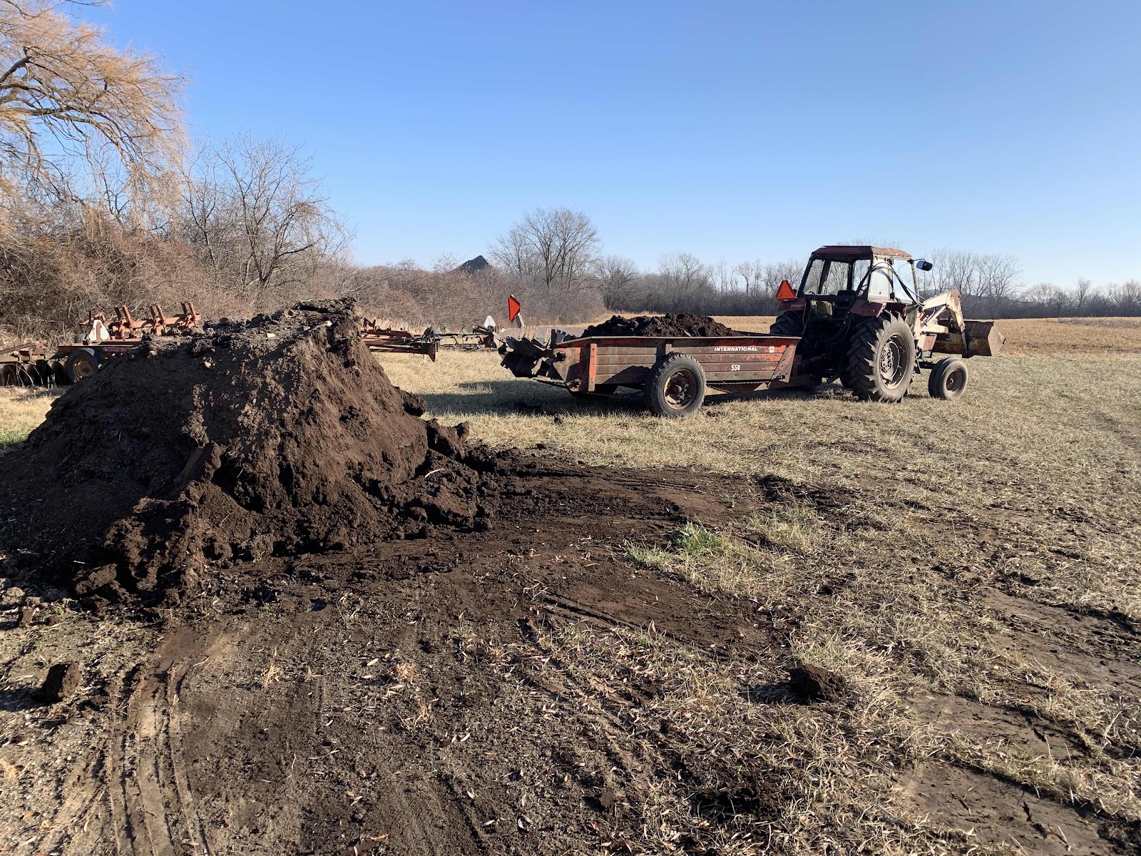
I built a wheeled plow for my team of miniature donkeys three seasons ago, and this plow is working well in my situation. Using a three-abreast team of miniature donkeys, I've been able to plow up pasture, red clover, winter wheat/rye cover crop, and corn stubble. My homestead garden plot of 1/3 acre has been tilled exclusively by my three donkeys for the past few years, and the moldboard plow has made a dramatic improvement in our ability to handle trash and terminate live cover crops or weeds. The soil is more productive with good plowing.
Developing the wheeled plow for my donkey team took some experimentation and several stages. Although I have used a walking plow, I now prefer the wheeled plow. I like that the wheeled plow runs in the furrow by itself, so I can focus all my attention on driving the team. The wheeled plow can also tolerate more side draft than an ordinary walking plow, which allows me to work with a three-abreast hitch. Overall, wheeled plows are a little more forgiving than a walking plow, which require a very accurate draft line and adequate suction. My wheeled plow in it's current form is working exceptionally well, and I hope you find some worthwhile information in the following description of the project.
The first step is to find a plow bottom that you like. Since my team is so small, I looked for the smallest plow bottom possible. I learned that David Bradley sold a line of walk-behind tractors through Sear for many years, and these tractors had a 6 ½” moldboard plow with a rolling coulter. The David Bradley bottom has a long moldboard with a gentle twist. I found one on Craigslist in good condition and purchased it for $75. There were similar, garden-sized plows made or sold by Brinly, Simplicity, Bolens, and Ariens. Brinly still makes a 10” moldboard plow for pulling behind a lawn tractor. All of these plows have a screw-jack adjustment to set the working depth. This style of depth adjustment will facilitate making a raise-lower mechanism for the finished wheel plow.
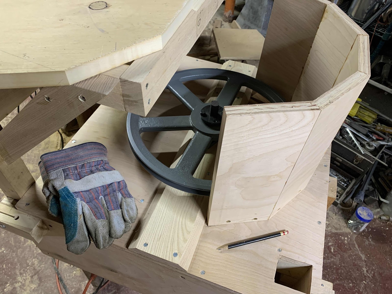
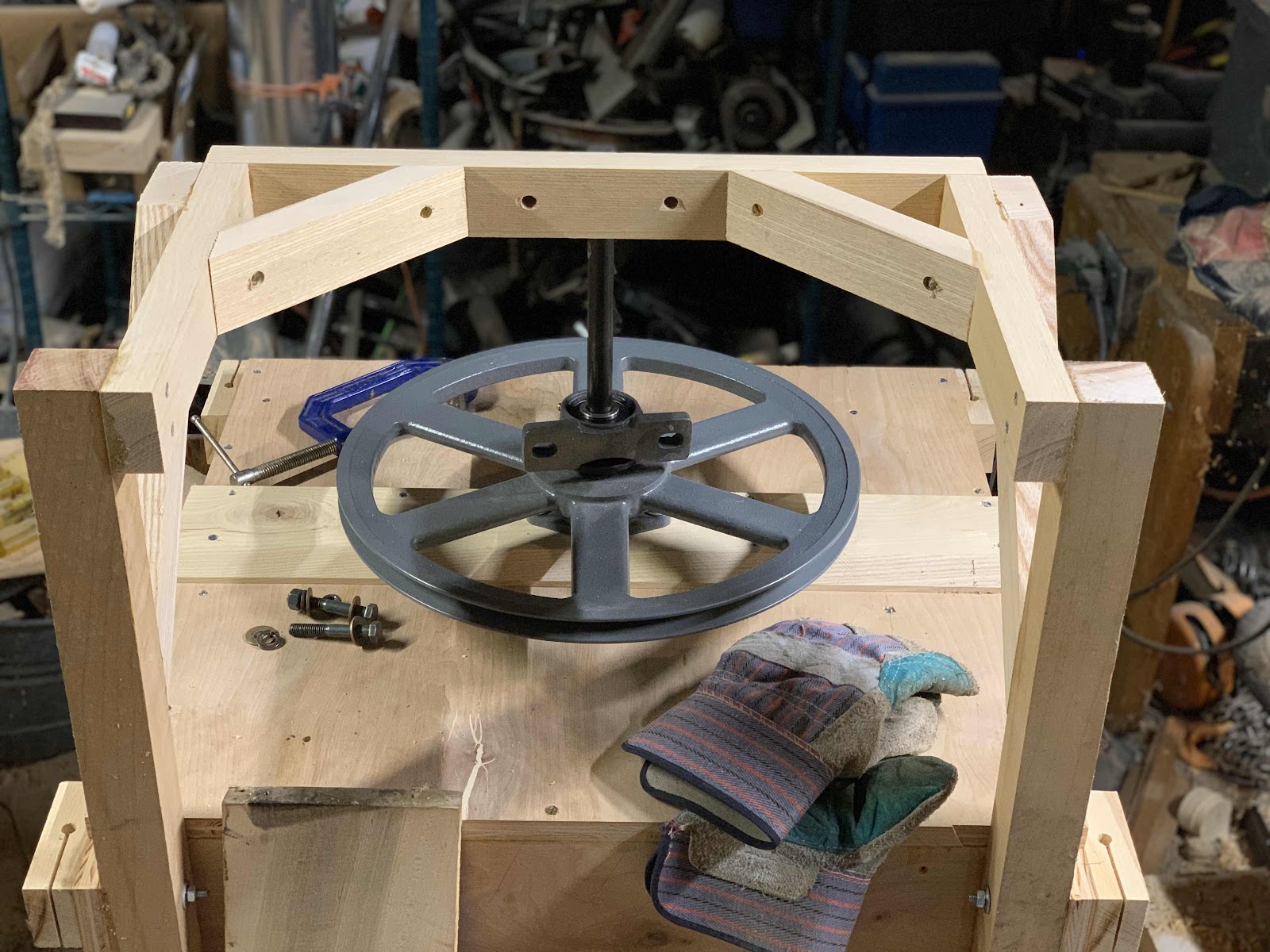
Next, find a set of wheels and get them mounted onto an axle. On my plow the axle is about 22 inches wide, and it's mounted with the furrow wheel set 9 inches to the right of the plow beam. The axle will be canted, that is, attached to the plow beam at an angle, so that the plow bottom will run flat in the furrow. The wheels run at two different depths any time the plow is in a furrow. In a four-inch furrow, for instance, the land wheel is going to be four inches higher than the furrow wheel. To keep the plow bottom flat, the wheels need to be mounted at different heights.
Most sulky plows have an independent adjustment of the land and furrow wheels, so that the bottom always runs flat. For this project, we're just going to assume an average plowing depth and mount the axle at the appropriate angle. To find this angle, set the plow down on a flat surface. The bottom of the plow must lie flat on this surface. Next, pile up some blocks equal to the depth you plan to plow at. For small plows like the one's were talking about, I suggest four inches. A small plow can't go much deeper, and it will have trouble staying in the ground if the depth is less than three inches.
Now put the axle, with the wheels mounted, about two feet in front of the plow point. The screw jack adjustment on the plow should be about 2/3 of the way towards the deepest setting. Now put the landside wheel onto the blocks. This is how the plow will be running in the field. The furrow wheel stays down in the furrow with the plow, and the landside wheel runs on unplowed ground. Now you can start fabricating the joint between the axle and plow beam.
I suggest using bolts, or tack welds, whenever possible, while building and testing your plow. It helps a lot if you can change things easily while testing. You can learn a lot by taking the prototype out to some soft ground or to a sandbox, and pulling it by hand. (I used soil from my compost pile for early testing.) The position of the furrow wheel is especially important. The furrow wheel should run snugly in the left hand side of the furrow (for a standard right-hand plow). The land wheel can be almost any place to the left of the plow beam. Mine is about 18” to the left of the plow beam. A wider stance will make the plow less likely to tip over when turning to the left.
The basic wheeled plow without a raise-lower mechanism or a stability arm. The plow functions well in this basic configuation. The hitch point needs to be a little higher than the line of draft. By putting the hitch point slightly high, the draft develops some down force on the wheels. The furrow wheel has a better chance of tracking nicely in the furrow if there is some down force. Use your chosen draft animal and figure out how high the line of draft will be. There should also be some adjustment of the hitch point from left to right. This adjustment will allow you to make changes in how much land is plowed on each pass, and to adapt to one, two, or three animals abreast. Make your hitch plate, and drill multiple holes in it to create a left-to-right range of adjustment.
The plow can be used with just two wheels and a hitch point, and no further modification. It's simple and fairly rugged. The main drawback is that it will be difficult to engage and disengage. You either have to turn the screw-jack about 8-10 times at the beginning and end of each row, or lift up the plow bottom with one hand while turning your team around with the other hand. I ran the plow like this for a few sessions, and I learned a lot. But I knew that a system for disengaging the plow was needed next.
After trying several engage-disengage mechanisms, I have settled a simple cam lever that works well. In principle, disengaging the plow is straightforward. All that is needed is for the angle of the plow to change enough so that it loses it's tendency to dig into the soil and starts skimming the surface. I considered (and used) a lever that raised the front wheels, and also made a lever in back with a locking mechanism. The lever that raised the front wheels made the plow very top-heavy and prone to tipping over. The lever in back only had six inches of travel and did not provide enough mechanical advantage to change the plow angle easily. The plow only needs to tilt upwards about 15 degrees, but when the plow is buried under four or five inches of sod, this takes a lot of force.
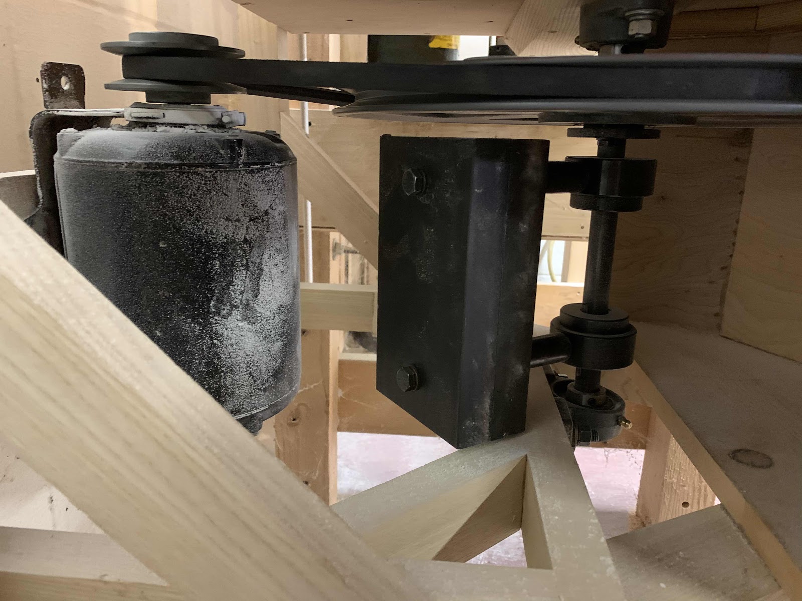
The plow in the disengaged position. Note how the cam lever has forced the front mounting of the screw-jack upwards, which tilts the plow point up and prevents the plow from digging in. One of the bolts that previously secured the front mounting of the screw-jack has been removed, so that the triangular mount now pivots on the rear mounting bolt. A 1/2” spacer has been bolted in between the two triangular mounting plates to stabilize the front screw-jack mount, and to prevent the mount from tilting too far forward.
The solution I've settled on is to adapt the anchor point of the screw-jack so it can be moved using a lever about 30 inches in length. A 30 inch lever has a lot of force to move the screw jack, so the plow point is forced up enough to guide the plow back up to the surface. The lever is pushed forward to begin plowing, and lifted at the end of the field. There is no need to start or stop the team at the beginning or end of a furrow. The cam is drilled slightly over-center so the lever stays up when the plow is disengaged. I also added a heavy-duty spring to help force the tip of the plow downward when the lever is in the “engage” position.

The engaged position, ready to start a furrow. The cam lever has swung forward, and the spring is now forcing the plow point into the ground. Once the plow is running, the downward force of the plow makes the spring superfluous.
The plow is a little unstable when being pulled over the headlands, especially in tight turns when first opening up a field. To help keep the plow upright, I added a stability arm that drags on the ground any time the plow tips too far to the right. The stability arm extends about 22 inches to the right and is is fixed directly to the plow beam. The plow rarely ever tips to the left, since the landside wheel is far enough over to the left to prevent this. But the plow by it's nature is a little tippy to the right, and making tight turns on the headlands just exacerbates the problem. The stability arm, made of angle iron with a skid, works very well to keep the plow from tipping over and creating a problem.
The final modification is the addition of more surface area to the landside. I found my plow did not always run straight in the furrow, especially in wet soil. The considerable surface area of the moldboard was pushing into the landside with more force than the land could resist. The plow was actually pushing some soil to the left, instead of running straight and pushing all the soil to the right.
After looking at some old walking plows, I felt that my David Bradley plow needed more surface area on the land side. I cut a piece of 1/2” plate to fit and bolted it directly onto the plow frame. I had to shape this piece of steel with a grinder to make the contour match the existing landside. The plow is running better now with this addition.

Moldboard plowing is one of the most thrilling aspects of animal-powered farming. When everything is right—the plow, the team, and the soil—plowing is just beautiful! The satisfaction is doubled when you have built your own plow. I encourage you to take the ideas in this article and go build your own plow. Remember that in the 1830's, John Deere was just another blacksmith. During the period in which he lived, there were many blacksmiths hammering out their own version of the perfect plow. Make your plow, test it, and share your ideas with the community.
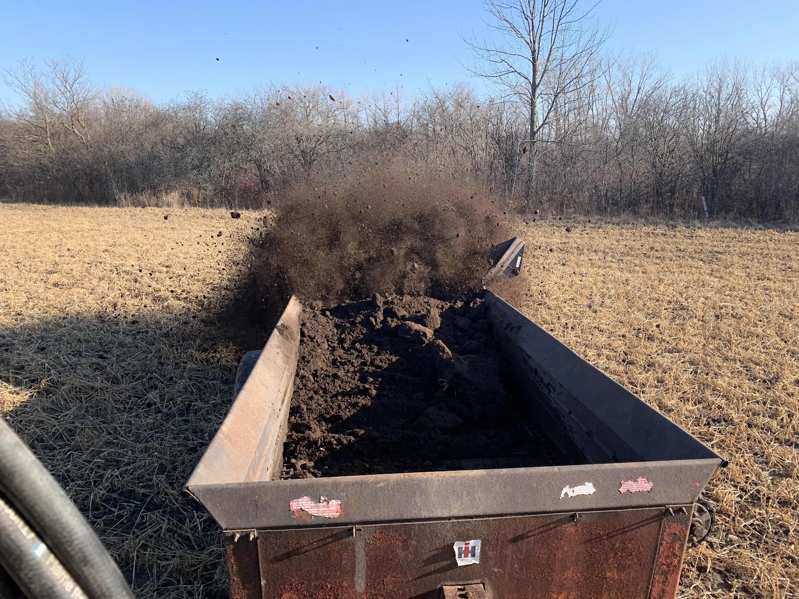
Moldboard plowing is an important part of small-scale, animal-powered farming. Plowing controls weeds, buries trash, and prepares a seedbed. For those of us who choose to farm without chemicals, it's almost indispensable. Although some organic farmers are having success with no-till methods, I doubt there are many who have really dispensed with the plow completely.
The wheeled plow is an excellent option for people working with smaller teams, or for teamsters without access to a good walking plow. The wheeled plow takes care of itself while you focus on driving the team. Wheeled plows are more efficient than a sulky plow, where the animals are asked to pull both the plow, and the teamster riding on the plow. I hope farmers working with draft animals will consider walking, instead of riding, whenever possible. For many of us, our first experience of draft animals was seeing a team of horses pulling people in a carriage, and we have inherited a subtle bias that draft animals exist to “give us a ride.” Whenever the scale of the operation allows, I think it's much better, and much more meaningful, to walk in the field with your team.

When you are ready to build your plow, some background in the theory of moldboard plowing is very helpful. I suggest seeking out this excellent, and free, source: “The Oliver Plow Book: A Treatise on Plows and Plowing,” by Charles Allen Bacon. Published by the Oliver Chilled Plow Works in 1920, it's available online at
https://books.google.com/books?id=nAY9AAAAYAAJ. This book describes the basics of draft angles and suction, which are important to understand to make a moldboard plow run well. There is a lot of other information in this book, as well.
I'm happy to answer questions if you're working on your own project. Reach me using the “Contact Us” page on my website at www.AnarchyAcres.com. Good luck, and happy plowing!
Moldboard plowing is an important part of small-scale, animal-powered farming. Plowing controls weeds, buries trash, and prepares a seedbed. For those of us who choose to farm without chemicals, it's almost indispensable. Although some organic farmers are having success with no-till methods, I doubt there are many who have really dispensed with the plow completely.
The wheeled plow is an excellent option for people working with smaller teams, or for teamsters without access to a good walking plow. The wheeled plow takes care of itself while you focus on driving the team. Wheeled plows are more efficient than a sulky plow, where the animals are asked to pull both the plow, and the teamster riding on the plow. I hope farmers working with draft animals will consider walking, instead of riding, whenever possible. For many of us, our first experience of draft animals was seeing a team of horses pulling people in a carriage, and we have inherited a subtle bias that draft animals exist to “give us a ride.” Whenever the scale of the operation allows, I think it's much better, and much more meaningful, to walk in the field with your team.

When you are ready to build your plow, some background in the theory of moldboard plowing is very helpful. I suggest seeking out this excellent, and free, source: “The Oliver Plow Book: A Treatise on Plows and Plowing,” by Charles Allen Bacon. Published by the Oliver Chilled Plow Works in 1920, it's available online at
I'm happy to answer questions if you're working on your own project. Reach me using the “Contact Us” page on my website at www.AnarchyAcres.com. Good luck, and happy plowing!