Showing posts with label Projects. Show all posts

Thursday, January 30, 2020

Homemade cradle


A cradle is an attachment to a scythe which gathers the grain stalks as they are cut. Without a cradle, cutting grain with a scythe is not possible. The scythe will scatter grain stalks in a swatch without any organization, and the time spent picking up each one is longer than if the scythe was discarded for a hand sickle. To cut grain with a scythe, you need some kind of cradle.

The multi-fingered grain cradle is a purely American development, appearing sometime in the late 1700’s. Using a cradle, a person can harvest two acres of wheat per day, about triple the production of a hand sickle. Cradles were still used well into the 20th century, and the last US patent for a grain cradle is from 1924.


I made this cradle a few years ago and it has been working fine for me.  This is an old american style scythe and the cradle is mounted by a simple steel bracket to the hardware already being used to mount the blade.
Today, however, it is difficult to find a serviceable cradle. Not many have survived without rotting, or warping, or both. The following is a method I have used to make grain cradles. If you have access to a table saw, wood glue, and a few clamps, it’s a pretty easy project.

The most intimidating part of a cradle are the fingers, which need to be long, strong, and curved. Historically, the fingers were steam-bent, but we’re going to use the technique of wood lamination. To make the fingers, you’ll need a piece of wood at least 3” thick and clean of knots. Almost any kind of wood will work. On the table saw, rip out three thin strips, around 3/16” thick, and as long as the blade of your scythe. We’re going to make a single, curved lamination with these strips to cut the fingers from.

Set up some blocks on a countertop and clamp the strips down. Adjust the blocks until the curve of the lamination matches the curve of the blade. When you are satisfied with the dry fitting, spread glue onto the strips and clamp everything down again. Clamping laminations always gets messy, and the glue tends to make things slide around. So be prepared with extra clamps, blocks, etc. Try to get even clamping pressure across the wood surfaces.


This fingers ended up 5/8" x 5/8".  The wood is douglas fir, and it's a little too stiff.  You need the fingers to be a little flexible so they can be adjusted to line up with the blade.
When the glue is dry, remove the clamps and clean up the blank. Working carefully on a table saw, rip out strips around 5/8” wide. These will be your fingers. Make four or five fingers, depending on your own preference. Historically, grain cradles had anywhere from three to five fingers. I have found four to be perfectly satisfactory.

Next, make a post to hold the fingers. Begin with some clear, strong wood about 1½” x 1½”. Cut notches every six inches for the fingers and glue them in place. Finished fingers should be one or two inches shorter than the scythe blade.

Mounting the fingers to the post.  I am using only glue and that has worked just fine for me.  It wouldn't hurt to use fasteners or add some wooden bracing.
The post and fingers will need to be mounted on the scythe. In the case of an American scythe, fabricate a steel bracket that can be slipped under the two nuts that hold the scythe blade hardware in place. In the case of an Austrian style scythe, you will have to fabricate a wooden bracket coming off of the scythe handle.

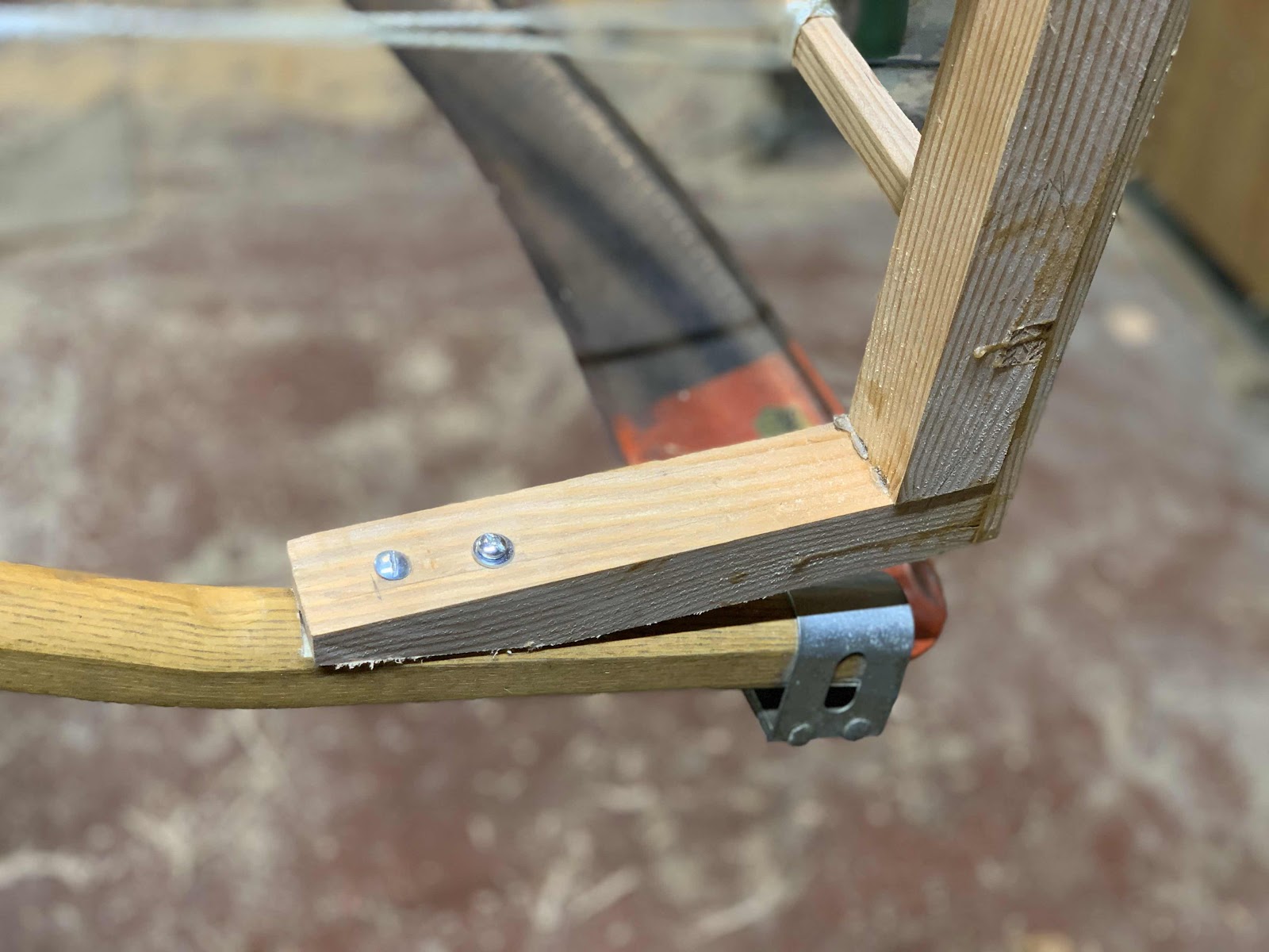
The post mounting, using two 10-24 bolts.  I don't want to drill too many holes through the handle, but I think it will still be strong enough.

Here's how I mounted the cradle to an american scythe.  I just made a bent steel bracket out of 3/4" wide stock and slipped it under the bolts that hold down the blade.  The strings will simultaneously adjust the fingers and add additional strength to the mounting.
The lowest finger should be around two inches above the blade. I have made mine with about a six inch gap, and they have worked just fine. But reliable historic sources recommend two inches.

Mount the fingers so that the tips are a little bit behind the scythe blade. The final adjustment will be accomplished with string running from the scythe handle out to each finger. The strings should attach to each finger about six inches out from the post. Tighten the strings until the tips are in alignment with the back side of the blade. The fingers need to grab each stalk of wheat that will be cut by the blade, without grabbing excess stalks.

The finished cradle.  This is the first cradle I've built for an Austrian style scythe.  Note how the post has been braced back to the scythe handle.  My impression is that a finger-style cradle might work best with an American style scythe, which has more curve and a shorter handle.  I'll find out at the 2020 harvest.
In the field, observe closely how the cradle and scythe blade are working together. If there are a significant number of stalks being cut and not cradled, or a significant number of stalks being cradles and not cut, the whole thing gets messy in a hurry. Be prepared to raise or lower how you hold the tool, so that everything lines up with the standing wheat. If the crop is standing straight, cradling goes very well. If there is any kind of lodging in the stand, cradling may not work well. If you have a choice, try to work with stalks leaning slightly away from you. It’s nice if you can work with the wind at your back.

There are two options in how to swing a cradle in the field. The most elegant is to cut and deposit the wheat in one stroke. Swing the cradle as you would an ordinary scythe. When the last stalk is cut, stop the swing abruptly without raising the blade from the ground. The cradled stalks should fall over in one neat bundle. The next swing of the cradle will deposit the next bundle perfectly in line with the previous. Now it is easy to come by later and gather the cut grain into whatever sized bundles you want.

The second option is to turn the blade sharply upwards after the last stalk is cut. Now all the wheat from the swing is securely in the cradle, and you can drop it anywhere you want. The mower might choose to make piles of three or four swings each, enough for one bundle. This method works fine but is slightly more physically demanding than the former.


Have a great harvest!


Sunday, December 22, 2019

Plansifter Project

I built a planetary sifter, or plansifter, this month to replace the bolting reel sifter I had been using for the past few years.  The bolting reel had trouble in the collection system, where flour would pile up underneath the reel and then get pushed over into the bran chute.  The problem was not acute, but it always bothered me that some of the flour was going out with the bran.  Hence the plansifter project.

A plansifter is a box filled with sifting trays.  The box hangs on flexible canes, and a motor with an intentionally out-of-balance counterweight causes the whole things to move in a circle.  The target is a gyration of 240-250 rpm, and a gyration of 62-65 mm.  See https://www.millingsystems.com/wnewsdisp.php?id=4040 for more information.

My unit is running at 250 rpm but the gyration is only around 40 mm.  I wish it were more but I'm afraid to put more counterweight on.  Right now I have 18 lbs of counterweight flying around about 6" from the shaft, which is already quite terrifying to me.  So for the time being I'll keep things as is.  However, the flour did not really move at all until I was well over 12 lbs of counterweight.  So if I ever need the unit to move more flour I will add more counterweight.

Here is the formula for gyration (thank you https://forum.bulk-online.com/showthread.php?20776-Counter-Weight-Problem):

The weight of the counterweights required will be equal to:
m = (M x r) / R

where
m = required total weight of all counterweights in pounds
M = total vibrating weight of screen (basket + mechanism + effective material load) in pounds
r = the required radius of vibration in inches
R = the radius from centre line of the mechanism shaft to the centre of gravity of the counterweight in inches

My plansifter is a simple two-part separation.  I built two screens, which I think have more than enough capacity for my 200 lb/hr mill.  The box is nominally 24" x 24" x 12".   I built the box a little taller than needed in case I want more screens at some point.  My target is 95% extraction and I currently use a 28 mesh stainless steel screen with an opening around 700 microns.

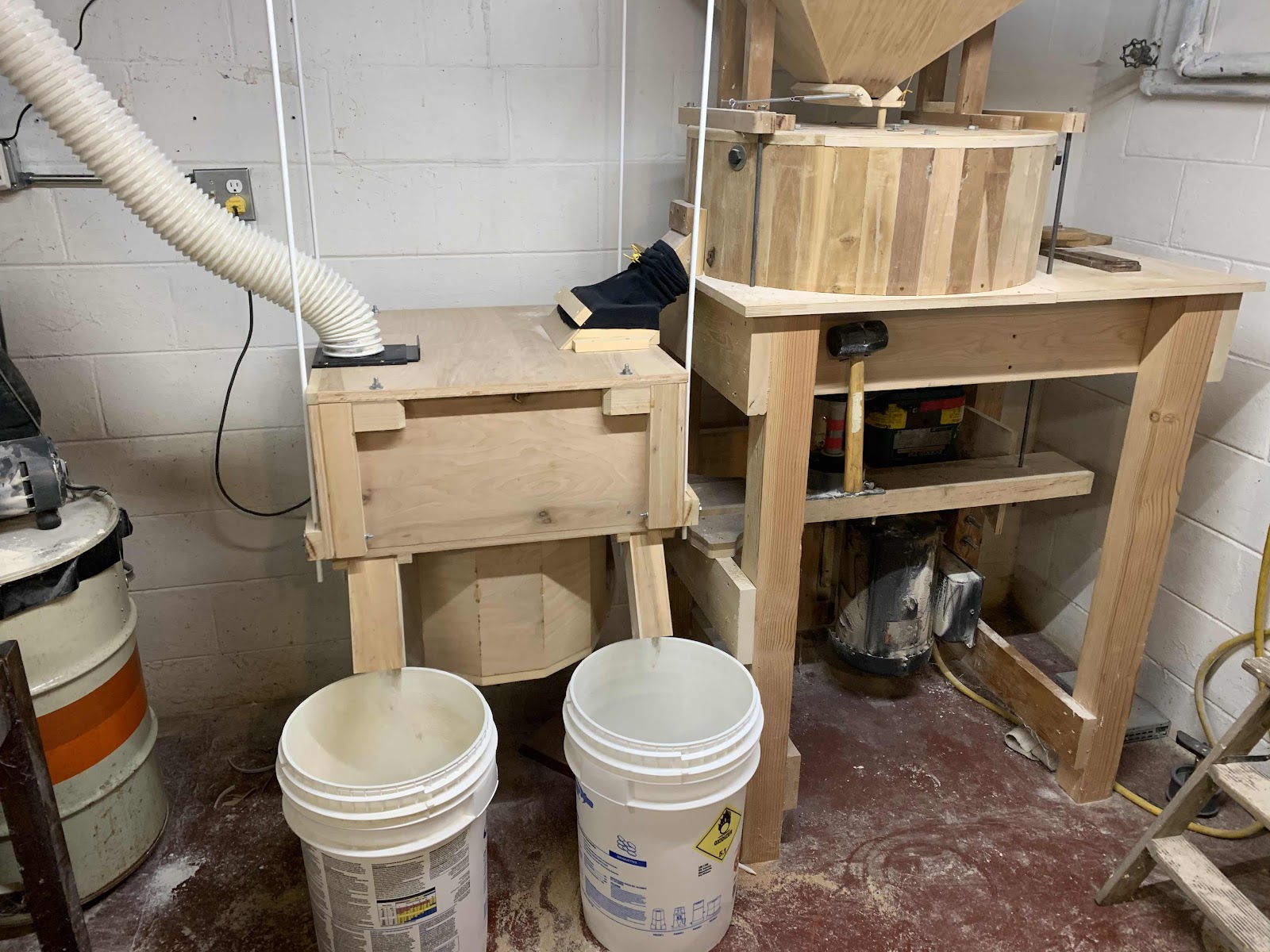
The new plansifter as installed.  I use a shop dust collector to create a slight negative pressure in the unit, which keeps my mill room remarkably dust free.  Flour comes out on the left and bran on the right.  The flour enters at the top right and is dumped directly onto the top screen.  Anything that falls through the screen gets pushed off to the side by the tray cleaners and falls to the bottom of the box.  The bran flows to the left and then drops down to a second screen, where it starts flowing to the right.  Anything that goes through the second screen also falls to the bottom of the box and out the left spout.  Basically you just have to seal up and baffle everything so that there is no choice about what media ends up where.  The constant shaking of the plansifter ensures that product will continue to flow.

Startup of the plansifter is a little dicey.  If it bumps the mill the unit will bounce hard and possibly cause damage.  But once it is up and running the unit is rock solid and stays put.  Apparently stable startups are an issue with commercial units as well.  See https://www.gwmfg.com/Pages/HS-tru-balance-drive.htm.

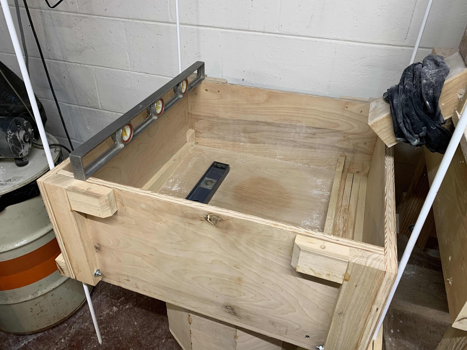
Leveling things off during the installation.  The wooden clamps I made for the canes worked so-so.  The top is held down with four bolts.  Prior to putting the top on, I add shims so that the tray stack is firmly clamped together.  The trays have ordinary wool felt strips between them to seal things off.  Of course, there needs to be a flexible connection for flour going in and out, since the whole thing is going to be shaking at 250 rpm.  I use an old long-sleeve shirt as a gasket between the mill and sifter.

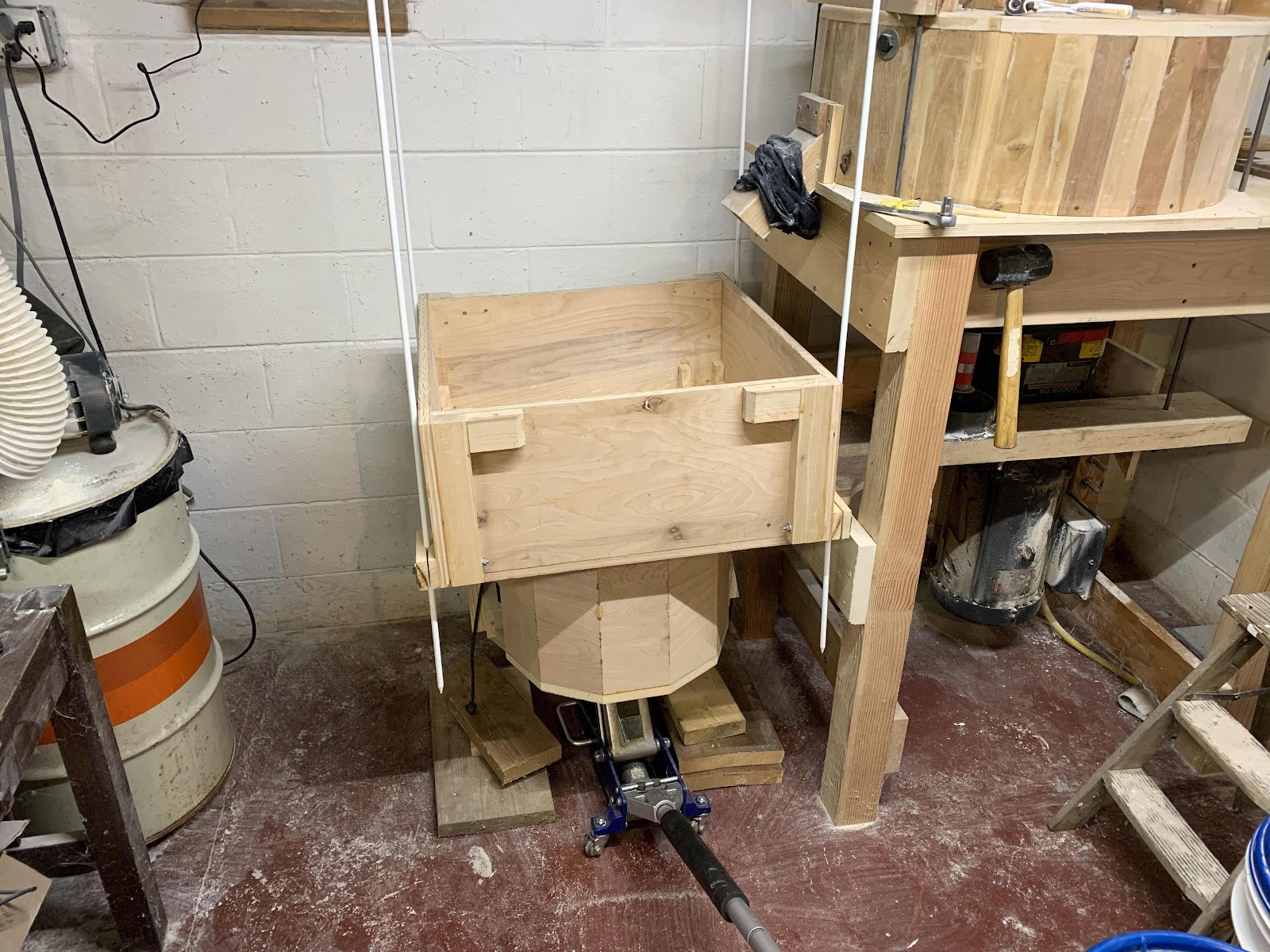
Installing the plansifter.  It hangs from the ceiling on four 3/8" fiberglass fence posts.

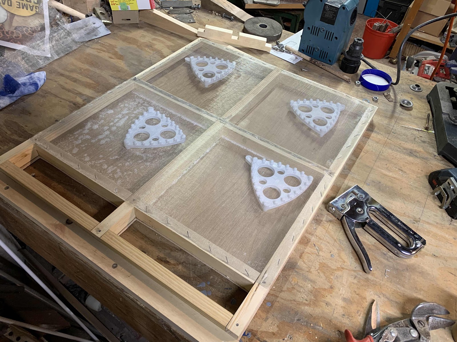
Here is my first sifter tray with tray cleaners and screen installed.  This style does not use backwire.  The bottom of the tray is perfectly flat.  The screen cleaners bounce around, keeping the screen clean and pushing the flour off to the sides.  Cleaners were easily purchased after contacting the folks at Filip in Germany: https://filip-gmbh.com/en/products/for-plansifter-sieves-without-backwire/.  The wood strips on the side are slotted so the flour can slide off.  See https://www.youtube.com/watch?v=-zrWWhUPOzE

Trial fitting.

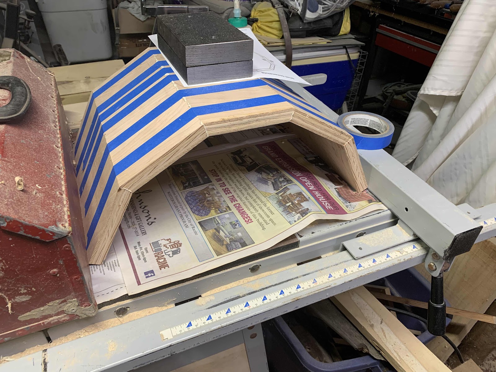
Gluing up a shield for the counterweight. Ultimately I glued it into place and it became part of the bracing for the counterweight shaft.  There is a nice stave calculator at https://uniontownlabs.org/tools/stave/.  Those weights being used to hold it down for gluing are the counterweights.  They are held in place on two 3/8" by 6" bolts off of the steel 3/4" shaft.

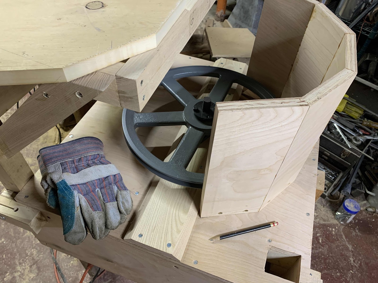
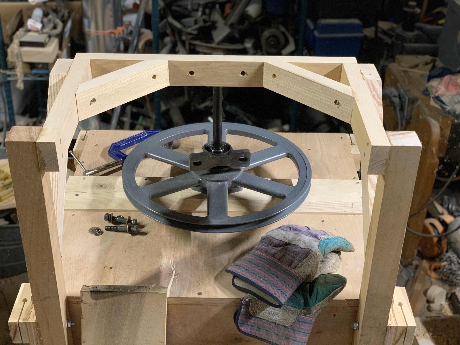
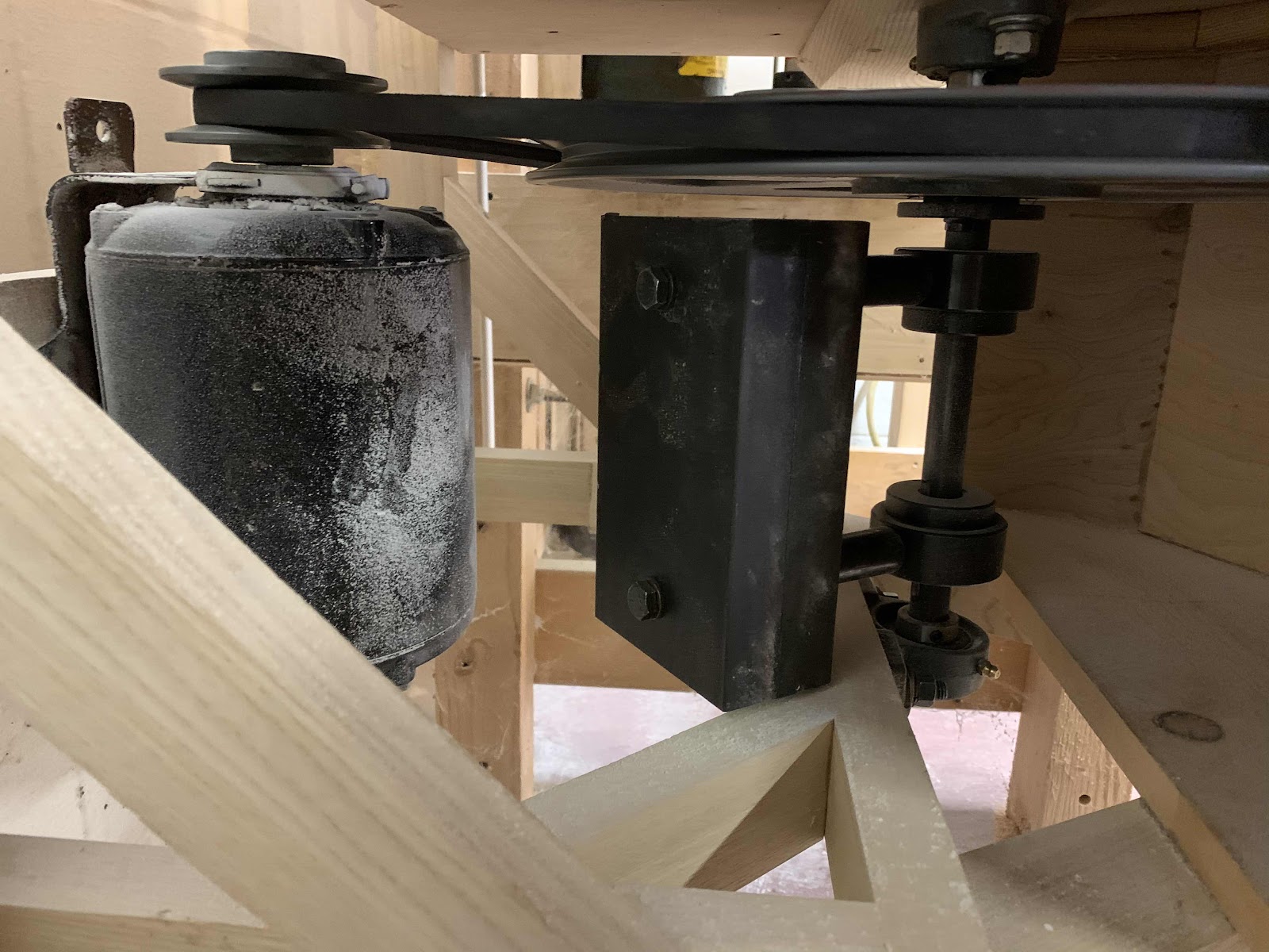
The reduction drive and counterweight shaft.  I had to use a 15" pulley to get down to the target of 240-250 rpm for the counterweight.  This size pulley weighs more than the motor, which is unfortunate.  The heavier the unit, the heavier the counterweight needs to be.  Ideally I would start out with a 1200 rpm motor which would make the reduction easier and lighter.
Machining the keyway on a harbor freight drill press.  Not very precise work, but good enough for a keyway.  I wanted everything to be as strong as possible, not knowing exactly where things would be stressed.

Here is the final motor and counterweight installation.  It's a 3/4" shaft.  I found two 3/4" gear hubs, which I drilled and tapped to accept a 3/8" bolt.  The hubs are held to the shaft with a square key and set screws.  The counterweights just bolt into the hubs.  Spacers are some thick-wall steel tubing.  The motor is an 1800 rpm 1/4 or 1/3 hp unit with an adjustable pulley to tweak the shaft speed.

Here is what it looked like the first time I fitted up a sifting frame.  Everything is perfectly flat, with the exception of the box floor.  If you look close at the bottom of the photo you can see where I am missing baffling.  I figured this out after the first run when I found flour coming out with the bran.

The plansifter needs to be strong--it will undergo a great deal of strain as it is being gyrated.  I chose to make corners with outside hardwood reinforcers.  Everything is glued and screwed.  The reinforcing stringers on one end will help support the counterweight shaft and bracketing.

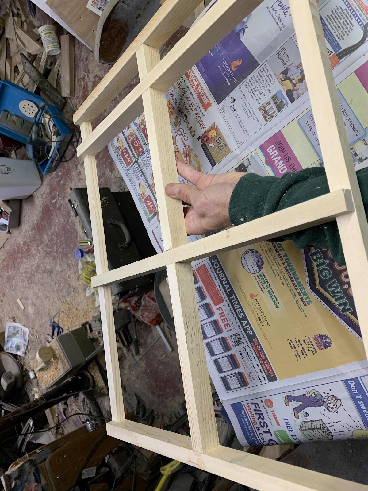
First frame going together.  The side pieces have some space underneath to allow the flour to fall through.  I used a dado head on a radial arm saw to make the corner joints.  After gluing the frame up, I nailed a piece of 3/16" plywood to the bottom.

Friday, December 15, 2017

Donkey Mill Project

I've had the idea for a donkey-powered mill for awhile, and recently I came across a good automotive differential to be the primary hub and gearcase for the project.  With typical abandon I went to work and had the basic machine running about 10 days later.


Sebastian was the test pilot for this project.  I hope to have three sweeps eventually and use the whole team.  A threshing machine will require all the power I can get.  This sweep is a carbon-fiber windsurfer mast, much stronger than it looks in the picture.  I might go for something a bit longer eventually.  The skid is just spiked into the ground right now.  The sheller is just sitting on the ground, too.

Here is how the differential looked the day I brought it to the farm.  The seller told me it was from a rear-wheel drive Mazda, but I have no way of confirming that.  It took some doing to get the old driveshaft and rear axle off.

I liked this differential because all three shafts terminated in nice 4-bolt flanges.  Easy for fabricating.

One of the axles needs to be prevented from turning.  This differential offered an easy solution--I added a piece of angle iron to serve as both mounting bracket and the stop-turn mechanism.  It got a little trickier, however, when I found that any pressure on the axle flange caused the gears inside to bind up.  I later learned that the seal around the axle is not very good, and oil leaks out.  If I get the unit inside again, I think I will clean it up and put some good silicone around the lower axle to keep the oil in better.

So I fabricated another mount to hold the unit up around the driveshaft flange.  Since nearly every differential has a modest gear reduction from the driveshaft to the axle, it makes sense to drive the donkey mill from one of the axles.  In theory there would be no problem attaching the sweep arms to  the driveshaft input.  You would just lose some rpm on the output shaft.  By driving one of the axles I'm getting about a 1.5:1 speed increase.  My donkeys pulling on 9' sweeps are doing about 3 rpm I figure.

Here I am using some bicycle sprockets to get an additional 43:13 gear ratio.  I used 1/2" shaft for my interim driveshaft, but now I wish I had used at least 3/4".  It looks like a potential area of weakness.

The long shaft coming out of the center is 1/2" water pipe.  Again, maybe I should have gone bigger.  I fabricated some simple flex couplings from pipe flanges, little pieces of rubber cow mats, and 1/4-20 bolts.  I put these flex joints at both ends of the 1/2" pipe driveshaft.
Here is the unit to receive the power coming off of the sweep.  Again, very quick and dirty.  I'd like to improve this with some kind of shut-off clutch and some additional shafts to make additional gear ratios easy to achieve.  I'd like to run a fanning mill and a small threshing machine eventually, in addition to the corn sheller.  The corn sheller made gearing pretty easy for the first time out, since it's made to run with a hand crank at around 20-30 rpm I think.  The final output speed tested was 30-32 rpm, with Cassie on the sweep.  Other items will require higher rpm and more gearing.  I felt good about using a v-belt for the final drive, since the slippage would provide some safety as I built up the system and learned how it worked.

After running about 100 lbs of corn through the mill, the 1/2" pipe shaft seems a little undersized.  It would buck under loads, usually when the donkey would slow down and the sheller get stuck with an ear of corn half way through.  I'd like to rebuild it so the shaft has a higher rpm, and therefore lower torque on it.  I think a second chain on the center before transferring power to the main shaft is a good idea.  Also, I'm wondering if I can find some sort of slip clutch to act a safety overload.

Thursday, November 30, 2017

Threshing Machine Project

I resolved over the summer that I needed to start working on a threshing machine.   The grain coming off the homestead plot is getting bigger every year, and hand threshing is a pain.  The wheat was especially a problem, and I left a lot of seed in the straw.

My threshing machine has to conserve seed and prevent cross contamination.  These are both nearly impossible if I use the combine as a threshing machine.  The combine can almost never be clean, and small batches of threshing will be very wasteful.  Due to the size and complexity of even a small combine (or old threshing machine), there is probably 10 lbs of seed sitting inside it at any time.  The test plot may only produce five or ten pounds of one variety of wheat in one season, so the scale is just not suitable.

I looked around for something to give me a leg up in building a threshing machine, but could not find anything.  I had resolved to build one from the ground up, using these plans as a departure point.  I thought I could at least get some old rasp bars from a dead combine somewhere, and that's where I found my leg up.

It turns out that nearly every Massey combine built has separate threshing drum for tailings, which they call a re-thresher.  While most combines (and old threshing machines) route un-threshed heads back into the main threshing drums, Massey thought it would be better to make a small, axial-flow head to deal with this stream.  The re-thresher is a little strange.  It feeds from the side and discharges at the top.  I think this makes it technically an axial-flow drum.  It's a bit like a combination squirrel cage fan and threshing drum.

Anyhow, these re-threshers are very well built and it had a lot of what I wanted to get the project going.  There are good rasp bars and solid bearings.  The concave is adjustable by adding or removing spacers under the concave bars.  Although I may try to make a true concave and change the flow to ordinary threshing drum flow, for the time being I am experimenting with it as is.


Here is what the concave bars look like.  I experimented with sunflowers, wheat, and beans.  For beans I removed all the bars.  There are spacers under the bars to change the concave clearance.  The beans were still getting cracked with the bars removed and the rpm reduced to 406 rpm.  Slower rpm might help.

So there is no separator right now, just a tarp.  The re-thresher throws the beans pretty far.


I threshed 25 lbs of beans in two sessions.  It went pretty quickly.

V-Plow Build Photos

I built a V-plow a couple winters ago for the team to clear work paths.  I can keep work paths open between the house and barn now very easily.  It clears a lot of snow very quickly, although there is not too much control.  It can get a little squirrely, and once there is an established snow bank it's hard to change the path.  But you can't beat it for quickly opening up a path.

Work photos are below.  Sorry if I'm a little hazy about some of the details.

The plow under construction.  I think those are 2x10's.  I have a small gait that I want to get through, so this plow is not particularly large.  It cuts a path around 6' wide.  The angle is 90 degrees.  In discussion with others I learned that a "pointier" design might possibly make the plow track better.


Tuesday, November 28, 2017

Snath

I made a snath for a new scythe blade that a friend gave me for my birthday.  I had planned on making it out of a solid piece of ash, but the tree I thought was an ash turned out to be an elm.  The wood was too far gone so I had to change plans.

The completed snath and blade.  I finished the wood in ordinary spar varnish.  There are actually 21 pieces of wood total!

I remembered a piece of clear Douglas Fir sitting in the basement rafters, so I decided to use that for the project.  I already had a good scythe that I liked, so I used it as a pattern.  The fir was cut to length and then ripped on the table saw thin enough to make the required bend.  I made a jig on the workbench, glued things up, and clampled the pieces together.  I think the main part of the snath was 6 pieces thick.

I began by making the straight piece, with a bend towards the bottom.  I used my workbench for the straight part, and clamped on a jig for the bend at the bottom.  It's a mild bend, less than 15 degrees.
For the lower handle I had to rip the pieces thinner, to make a sharper bend.  I did this in a separate lay-up.  I had to glue on extra small pieces to make the snath thicker in the area of the handles, and where the blade attaches.  I used attachment hardware from an english-style scythe.

I cleaned up the glue joints with a block plane, then went back to the workbench to jig up the lower handle.   I had to rip these pieces a bit thinner to get the bend I wanted.  The handle is glued onto the main part of the snath without any nails or screws.


The handles are some clear wood from the elm tree that I had hoped to make the snath out of originally.  I shaped the handles and then put a 7/8" diameter on the end.  The snath had 7/8" holes drilled in at the appropriate locations, and the handles were glued in place.  The entire snath is held together with ordinary carpenter's glue.

Here is what it looked like after a good shaping and sanding.  I think it is plenty strong but only time will tell.  It's a little fancy for something that is supposed to be workmanlike, but I enjoyed this project.  
Attachment hardware is from an ordinary English-style scythe that was rotting away in my collection.  The Tops blade from Scythe Supply was said to have a tang that works well with English-style scythes, and I only had to slightly touch it with a grinder to make it fit.  I like having this hardware since the Austrian-style clamp can slip so easily.

Friday, November 17, 2017

Rosie's New Harness

My illustrated children's book about Team Anarchy was published this week!  Look for it at the website, or Amazon, Barnes & Noble, etc.


Monday, May 22, 2017

Various

The moisture and cold are still not letting off!  Although there have been no unusual, late frosts, there has been plenty of wind, rain, and 40 degree days.  Aaaargh,

Simon and Nigel, during their shearing ordeal.  They actually got cleaned up pretty well this year.

The new disc hiller in action.  I have high hopes for it, since it has the capacity to make the wet, low areas of the garden more usable.  The first raised bed is a mix of peppers, tomatoes, and red potatoes.  As soon as I can work in there again, I hope to make several more beds for tomatoes and cucurbits.

Peppers went into the first raised bed on May 19.  The only good thing about our cold wet weather is that I don't have to worry about transplants drying out.  The peppers looked great after I got back to the farm from a weekend trip.

I put in four short rows of sunflowers, which I hope to harvest for seed.