Showing posts with label Stone Mill. Show all posts

Sunday, December 22, 2019

Plansifter Project

I built a planetary sifter, or plansifter, this month to replace the bolting reel sifter I had been using for the past few years.  The bolting reel had trouble in the collection system, where flour would pile up underneath the reel and then get pushed over into the bran chute.  The problem was not acute, but it always bothered me that some of the flour was going out with the bran.  Hence the plansifter project.

A plansifter is a box filled with sifting trays.  The box hangs on flexible canes, and a motor with an intentionally out-of-balance counterweight causes the whole things to move in a circle.  The target is a gyration of 240-250 rpm, and a gyration of 62-65 mm.  See https://www.millingsystems.com/wnewsdisp.php?id=4040 for more information.

My unit is running at 250 rpm but the gyration is only around 40 mm.  I wish it were more but I'm afraid to put more counterweight on.  Right now I have 18 lbs of counterweight flying around about 6" from the shaft, which is already quite terrifying to me.  So for the time being I'll keep things as is.  However, the flour did not really move at all until I was well over 12 lbs of counterweight.  So if I ever need the unit to move more flour I will add more counterweight.

Here is the formula for gyration (thank you https://forum.bulk-online.com/showthread.php?20776-Counter-Weight-Problem):

The weight of the counterweights required will be equal to:
m = (M x r) / R

where
m = required total weight of all counterweights in pounds
M = total vibrating weight of screen (basket + mechanism + effective material load) in pounds
r = the required radius of vibration in inches
R = the radius from centre line of the mechanism shaft to the centre of gravity of the counterweight in inches

My plansifter is a simple two-part separation.  I built two screens, which I think have more than enough capacity for my 200 lb/hr mill.  The box is nominally 24" x 24" x 12".   I built the box a little taller than needed in case I want more screens at some point.  My target is 95% extraction and I currently use a 28 mesh stainless steel screen with an opening around 700 microns.
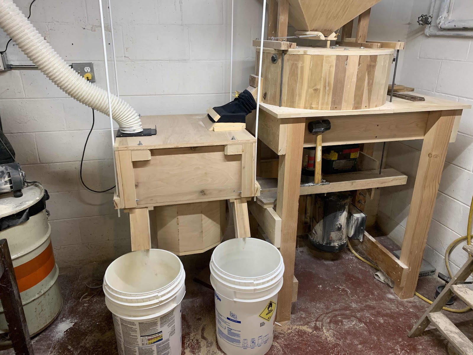
The new plansifter as installed.  I use a shop dust collector to create a slight negative pressure in the unit, which keeps my mill room remarkably dust free.  Flour comes out on the left and bran on the right.  The flour enters at the top right and is dumped directly onto the top screen.  Anything that falls through the screen gets pushed off to the side by the tray cleaners and falls to the bottom of the box.  The bran flows to the left and then drops down to a second screen, where it starts flowing to the right.  Anything that goes through the second screen also falls to the bottom of the box and out the left spout.  Basically you just have to seal up and baffle everything so that there is no choice about what media ends up where.  The constant shaking of the plansifter ensures that product will continue to flow.

Startup of the plansifter is a little dicey.  If it bumps the mill the unit will bounce hard and possibly cause damage.  But once it is up and running the unit is rock solid and stays put.  Apparently stable startups are an issue with commercial units as well.  See https://www.gwmfg.com/Pages/HS-tru-balance-drive.htm.

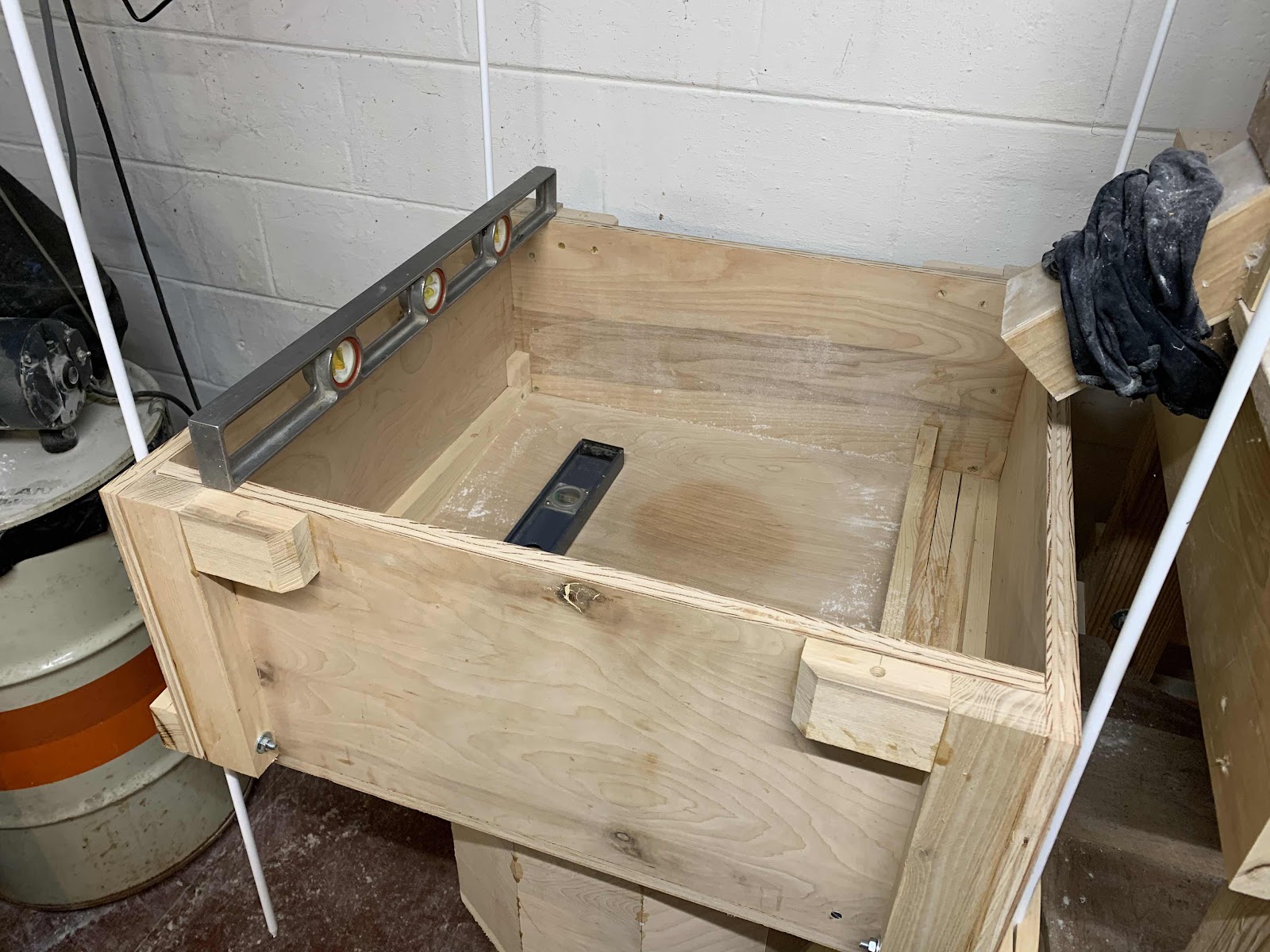
Leveling things off during the installation.  The wooden clamps I made for the canes worked so-so.  The top is held down with four bolts.  Prior to putting the top on, I add shims so that the tray stack is firmly clamped together.  The trays have ordinary wool felt strips between them to seal things off.  Of course, there needs to be a flexible connection for flour going in and out, since the whole thing is going to be shaking at 250 rpm.  I use an old long-sleeve shirt as a gasket between the mill and sifter.

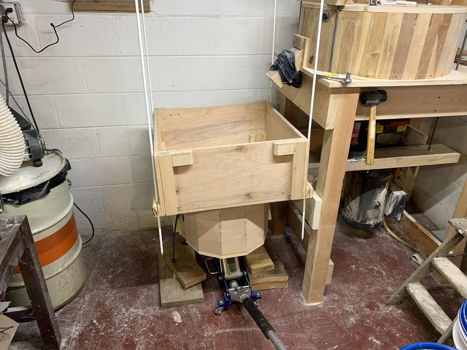
Installing the plansifter.  It hangs from the ceiling on four 3/8" fiberglass fence posts.

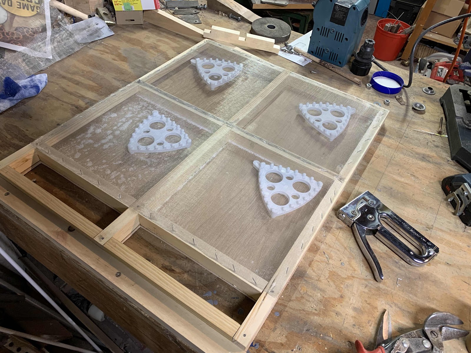
Here is my first sifter tray with tray cleaners and screen installed.  This style does not use backwire.  The bottom of the tray is perfectly flat.  The screen cleaners bounce around, keeping the screen clean and pushing the flour off to the sides.  Cleaners were easily purchased after contacting the folks at Filip in Germany: https://filip-gmbh.com/en/products/for-plansifter-sieves-without-backwire/.  The wood strips on the side are slotted so the flour can slide off.  See https://www.youtube.com/watch?v=-zrWWhUPOzE

Trial fitting.

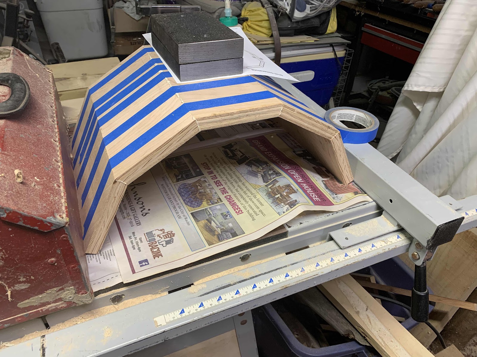
Gluing up a shield for the counterweight. Ultimately I glued it into place and it became part of the bracing for the counterweight shaft.  There is a nice stave calculator at https://uniontownlabs.org/tools/stave/.  Those weights being used to hold it down for gluing are the counterweights.  They are held in place on two 3/8" by 6" bolts off of the steel 3/4" shaft.

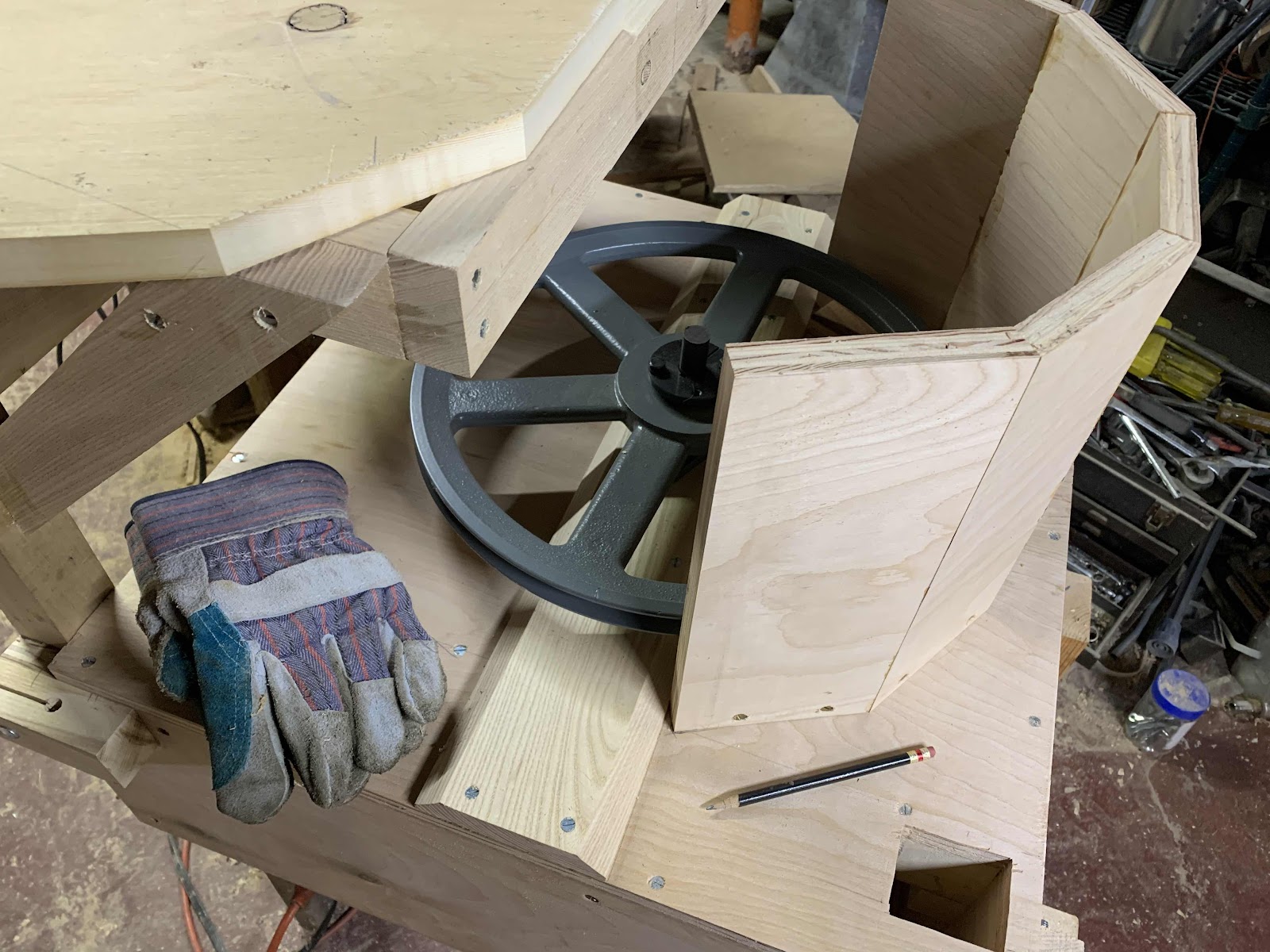
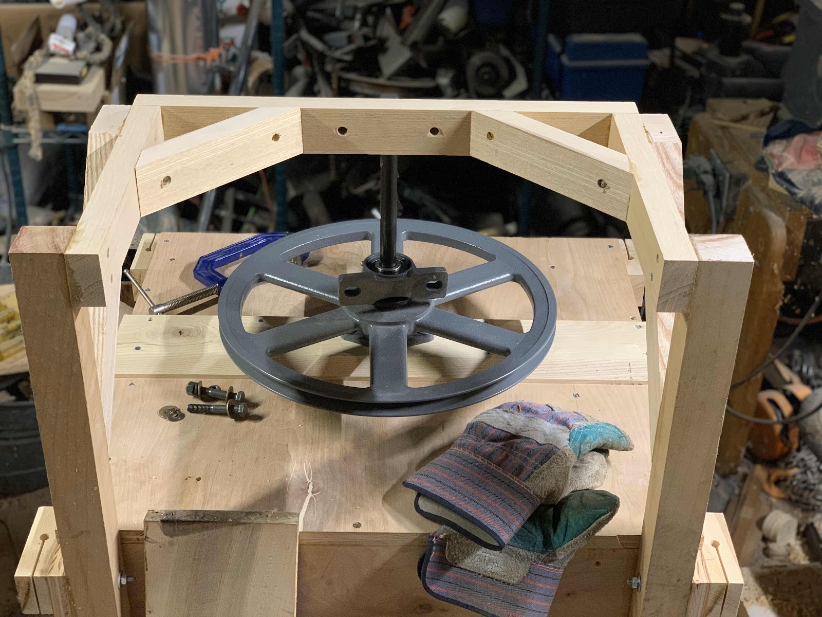
The reduction drive and counterweight shaft.  I had to use a 15" pulley to get down to the target of 240-250 rpm for the counterweight.  This size pulley weighs more than the motor, which is unfortunate.  The heavier the unit, the heavier the counterweight needs to be.  Ideally I would start out with a 1200 rpm motor which would make the reduction easier and lighter.
Machining the keyway on a harbor freight drill press.  Not very precise work, but good enough for a keyway.  I wanted everything to be as strong as possible, not knowing exactly where things would be stressed.

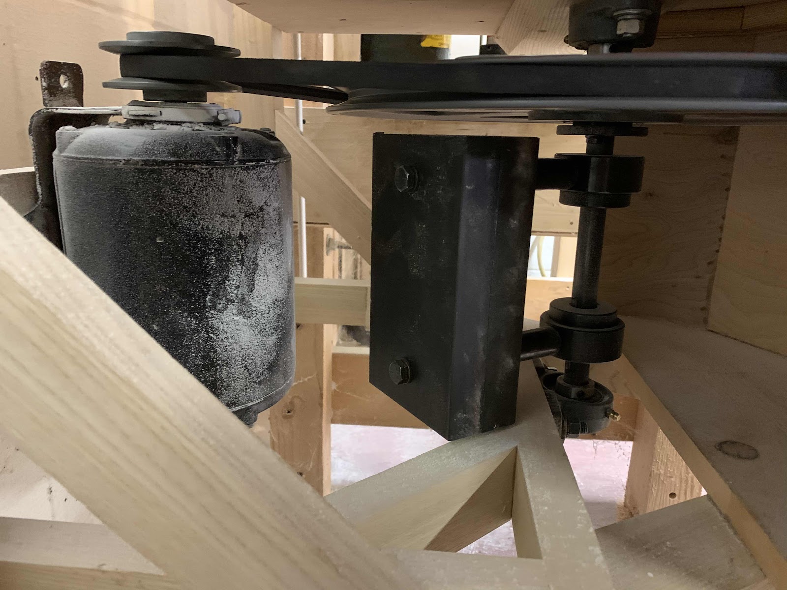
Here is the final motor and counterweight installation.  It's a 3/4" shaft.  I found two 3/4" gear hubs, which I drilled and tapped to accept a 3/8" bolt.  The hubs are held to the shaft with a square key and set screws.  The counterweights just bolt into the hubs.  Spacers are some thick-wall steel tubing.  The motor is an 1800 rpm 1/4 or 1/3 hp unit with an adjustable pulley to tweak the shaft speed.

Here is what it looked like the first time I fitted up a sifting frame.  Everything is perfectly flat, with the exception of the box floor.  If you look close at the bottom of the photo you can see where I am missing baffling.  I figured this out after the first run when I found flour coming out with the bran.

The plansifter needs to be strong--it will undergo a great deal of strain as it is being gyrated.  I chose to make corners with outside hardwood reinforcers.  Everything is glued and screwed.  The reinforcing stringers on one end will help support the counterweight shaft and bracketing.

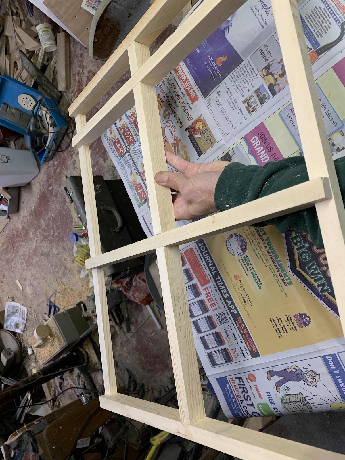
First frame going together.  The side pieces have some space underneath to allow the flour to fall through.  I used a dado head on a radial arm saw to make the corner joints.  After gluing the frame up, I nailed a piece of 3/16" plywood to the bottom.

Thursday, June 16, 2016

New motor on the mill

I have been limping by with a 2 hp electric motor on my 600 mm stone mill.  Normally these stones are installed in mills with 15 hp motors.  Since I am using a 9.6:1 gear reduction, I can't really capture 15 hp, but I do need more than 2 hp.  I have been running the 2 hp at 15-16 amps, and full load amps on the 2 hp is 13 amps.  I have been biting my nails and hoping not to burn out this little motor.

Anyway, my dream motor has always been a 5 hp, but single phase motors in this hp range are actually kind of rare.  3 phase is much more common once you get past 2 hp.  So craigslist is full of 3 phase 5 hp motors for ~ $100, but never a single phase.  Until last week, when a brand new, in the box, single phase 7.5 hp showed up on craigslist, for $150.  Score!

It's an absolute beauty, and a TEFC enclosure to boot.  I had to spend a day learning about couplings, though, since the new motor has a larger shaft.  The newer type jaw couplings are inexpensive and more tolerant of the grid coupling that I had been using.  The one I installed runs very quiet and smooth.

I did the first run on Thursday and found I was running around 19 amps.  According to the power curve specs, this should be around 4 hp.  Which is perfect, since the gearbox has a max hp of 4.65.  I did not mill enough to get a good measure of speed, but I think it was milling over 200 lbs/hr.  This is a good rate, being about as fast as I can feed the hopper and bag the flour.


It's hay season in this part of the county so I cut the rest of the red clover on Thursday.  I can't believe people ever did acreage of hay by hand.  The clover is very hard work, and a lot of it was knocked down which made it go three times as slow.  I plan to rake it up and store it in the barn for the herd.


Sunday, June 12, 2016

Garlic Scapes!

I've been waiting 11 months for garlic scapes, and they are finally here!  I'm so happy.  They go in everything for the next 6 weeks--in my scrambled eggs, on pizza, and in stir fries.  I did all three today!


I am harvesting onions and getting small leaves of swiss chard plus all the beet thinnings I want right now.  The spinach, alas, never took.  At least two plantings were as dead as a door nail.

The 10th Avenue Red Fife field is weedier than I had expected.  I will have to be prepared to clean the seed immediately after harvesting, otherwise the moisture from the weed seeds can spoil the wheat.

I scored a fantastic electric motor on Craigslist yesterday.  I will use it on the Model 600 mill and I hope this will make it much more productive.  Right now I just have a 2 hp motor on it, and I am always pushing the motor past it's safe amperage rating.  The only issue with this motor is that it's rated 7.5 hp, while my gearbox is only rated 4.6 hp.  I will need to limit the amperage so as not to exceed the rating and trash the gears.  This should not be too much trouble.


The new shoe on the seed cleaner is basically set to go.  The ball trays are not what I had hoped--the balls are not bouncing all that great.  I expect to be messing with it once I have a harvest to test it more.  The slope on the scalping screen is about 11 degrees, much higher than stock.  I am hoping this will let whitecaps and straw scalp off easier than before.


Monday, February 15, 2016

Putting it together

So after a little more than two weeks of work the Model 600 is up and running!  Here is how it looks in it's new home, hooked up to the bolting cabinet.


Gluing the top onto the tun (casing).  The staves actually did not stay true and the entire housing is kind of squashed, although you can't see it without a measuring tape.  I made the tun to be one-piece, meaning that the upper millstone has to slide out the bottom.  I managed a nice fit but perhaps a little too tight.  I'm not sure if the stone would come out in the middle of summer when the wood is swollen with moisture.  The upper millstone has 3 large thread inserts around the circumference, and at least 6 smaller ones on the top, in no particular pattern.  I am using bolts in all of them.


So here is what it looks like without the tun.  The game is that the upper millstone has to be perfectly supported in space so that the lower millstone can be raised up to just barely touch it, in perfect alignment.


This hopper is a bit small but I had already made it for another project so it will do for the time being.  The shoe is so-so and when I get around to building a larger hopper I will try to make a better shoe.


Belt slippage became an issue on the second run of the mill.  The runner stone would start slowing down if the grain was fed too fast.  I built the mill with two-belt pulleys because my free two hp motor came with one already on the shaft, and it seemed about right.  But running with two A-sized belts I am getting slippage.  I looked online and determined that in this circumstance a single belt can only be expected to transfer about .7 hp.  Keep in mind the rpm coming out of the gearbox is 180 rpm.  The driver pulley has an A pitch diameter of 4.4 and a B pitch diameter of 4.8.  The pulley on the spindle is a 5/5.4.  I might do a little better with B belts, but I think a more drastic solution is required.  So for now I just tightened the belt as much as I dared.


I don't want to tighten the belt too much because it starts messing with the stone alignment and pulling on the upper bearing, which needs to allow the spindle to slide through when the runner stone is raised and lowered.  So my long-term solution was to order some three-belts pulleys.  This was easier said than done because sheaves of this type can get expensive.  The ones I finally found were only about $40 with the bushings, but then belt size became a problem.  The new sheaves take a 5V belt, and those don't usually come in sizes less than 50" (my ideal is a 41" belt in this space).  Anyway, I finally found some 45" 5V belts online and I think there is just enough room underneath to slide the power unit over and tighten the belts.  

There is a lot of hemming and hawing in this area.  Large sheaves can get expensive--several hundred dollars is quite common.  The next mill I build will probably not have a gearbox, so reduction will have to be by belt.  The European mills using a 600 mm stone run the stones at 480 rpm, which would take a more than 3:1 reduction with the belt drive.  Furthermore, to get enough torque at that rpm requires a serious motor, in the 10-15 hp range.  5 hp is about the max you can expect to run off of single phase 220 v electricity, so things start to get messy and expensive.  I wanted to stay on single phase 220, and the 2 hp motor I source was really nice because it only draw 13 amps at full load.  I can use No 12 wire and a 20 amp light switch to control it, but any bigger and I will need a special motor start switch.  I wanted to keep this project sane and simple.  

I'm really glad I took the time to weld up a good adjustable bearing base for the lower bearing.  I can really tune up the alignment quickly and accurately and get the stones singing, like they should.


Note the 3/8" rods clamping the tunning down to the table.  The lower stone will be pushing up into the fixed stone, and that stone needs to be able to counteract that force.  This is where this style of mill departs from most stone mills built prior to the 20th Century, where it was normal for the top stone to turn and the bottom to remain stationary.  In the old style, the pressure is limited to the weight of the runner stone, whereas in this style the pressure is created by the bridge tree pushing the runner stone up to the bedstone. 


I never did a budget but I think this cost me around $1500 to build.  The millstones were $1000 shipped to the airport, the gearbox $85, and I spent $75 at the machine shop.  The motor was free and a lot of the wood was also free.  There were bearings and a shaft to purchase, and two bushings that I used to make fittings with.


Saturday, February 6, 2016

Model 600

I have been anxious to build a larger mill ever since the first one got going.  After finding an acceptable source for stones in Denmark, I wired out the money and did not have long to wait.  It turned out that air freight was the cheapest so in a week or so the millstones were waiting for me in a bonded warehouse.  I made purchase terms CPT (cost paid to) Mitchell Field, again to save money, and I also did the customs clearance myself.  It was pretty easy.  The hardest part was the stones themselves--shipping weight was 360 lbs!  I rolled the fixed stone into the house, this one is a little larger than the runner stone and I think it weighs around 200 lbs.  The working area is 600 mm in diameter, and overall it is a bit bigger (27" across the top).


Here is the frame going together.  I used 4 x 4 Douglas Fir legs, 2 x 8 stringers, and some high-quality plywood for the top.  The bridge tree is a solid piece of white oak, and the jack is 3/8" rod that I threaded to 16 tph.  The construction is a little weird since I want to be able to disassemble it next year and get it up the stairs, which are quite narrow.


Here you can see the thrust bearing and the adjustable housing I made for it.  The runner stone is basically sitting on this bearing, and the bridge tree can raise and lower the spindle shaft.  The bearing housing is adjustable so that I can "tram the spindle," ie, align the runner stone to the fixed stone.  The lower bearing is an ordinary farm bearing.  I could not find the thrust specs for it so I will just wait to see how it does.  The shaft is 1 1/2".  The 9.6:1 gearbox is a lucky find from craigslist, otherwise I was looking at a double reduction drive to get the speed I want.  This will drive the mill at around 160 rpm I think.


Here is the spindle coming through the mill table.  The tapered bushing was custom made for me at a local machine shop.  I welded up the other bushing to fit into a keyway in the runner stone and drive the stone. 


The spindle has two flats on it so it can tap on the damsel while running and keep the grain flowing smoothly.


Another shot of the lower thrust bearing.  Bearing and pillow block came from fleet farm, and I had to trim the corners of the pillow block to fit my adjustable housing.


Lowering the runner stone into place for the first time.


The runner stone wobbled on the tapered bushing, which was a surprise.  It thought it would lock on perfectly.  I ended up slotting the bushing so that the taper would lock it onto the shaft better, and I made this additional bushing to drive the millstone into the tapered bushing.  I also had to pick the stone up a couple of times and put some brass shim stock on the side of the taper in order to get the stone square to the spindle shaft.  The black bushing is a weld-type bushing that comes from Farm and Fleet.


Lowering the fixed stone into place.  These type of millstones are designed to have the lower stone moving, not the upper stone.  Having tried it both ways on the mini-mill, I really like the lower stone being the runner stone.  The eye never clogs up and a single grain kernel feeds instantly into the stones for grinding.


The upper stone needs to be suspended on something so I settled on making the housing out of staves.  I had to cut up at least 40 to get all the way around, using up a lot of nice wood in the workshop.


It was kind of exciting getting this thing glued up in a timely fashion.  The masking tape works wonders for gluing up staves.  Tape the outside, flip it so the inside seems open up, then brush the glue into the joints.  When the staves are put in place the tape does an amazing job of clamping everything together.  Cross fingers it cures up and makes a strong housing!


Wednesday, January 6, 2016

Up and Running!

The micro-mill model #1 is up and running now.  The basic specs are 250 mm Engstrom millstones, 3/4 hp electric motor reduced about 8:1, and a 12" diameter bolting reel with 640 micron stainless steel cloth.  Here is a decent video showing it under operation:


As-built the bolting cabinet is pretty much a requirement for making good flour.  Although the stones can be set to make very fine flour, for some reason a few poorly ground berries do get past the stones.  I worked very hard to get the stones flat but I think they are still flawed.  I'm disappointed that the factory did not provide me with well dressed stones to start out with.  I did learn from the quality person at Engstrom that small stones do not make the very best flour, but I think the lack of flatness is contributing to this problem.  Anyhow, this means that right now if I want to make 100% extraction flour I have to re-grind the bran to get enough bran into the flour.  If I ran the mill without the bolter there would be a tiny amount of unground berries in the flour.  I may try to set up the bolter with even courser cloth, so more bran will fall through, but I think the long term fix is larger stones.  I am trying to source 600 mm stones now.

Monday, December 28, 2015

Bolting Reel

I built a bolting (sifting) reel for the micro-mill, using old time mills like the one in Richfield as a pattern.  Although old sources recommend bolting reels that are 12, 16, or 20' long, I am hoping that I can get away with a much shorter reel since I do not sift very finely.  This reel is 12" in diameter and 24" long.  The mesh is 32 mesh T316 stainless steel bolting cloth, which has openings of 629 microns.

Here is the reel, 6 sided and built on a 1 1/8" dowel.


Here is the cabinet going together.  Angles are all 45 degrees, which works OK but I later found the flour can still hang up on the sides.


My Dad gave me a worm drive gearbox which had a 60:1 reduction.  This works great although the cabinet is resonating and the 1/4 hp motor is making a lot of noise.  The reel is turning about 45 rpm I'd say.  The bearings are all hardwood, lubricated with beeswax at this point.  I made the pulley on a lathe, quick and dirty.


Here is the bolting cabinet being tested with the mill.  Flour comes out of the mill and gets dumped inside the reel while it turns.  Flour comes out the small hole and bran the larger hole at left.  The extraction level is 90%, based on the first full bag I milled.  I am going to experiment with re-grinding the bran and increasing the extraction level.  This mill spits out cracked grains and it really needs to have the bolting attachment at this point. 


This 90% flour is really making a nice loaf.  Here is my second attempt, which was the lightest and chewiest loaf I have made so far:


Sunday, December 13, 2015

Millstone dressing

To improve upon my mill project I ordered a set of 250 mm composite millstones from the Danish company Engsko.  Unfortunately, the millstones would not produce good flour in the mill.  I made several attempts to carefully line up the stones, shimming the mounting of both the bed stone and the runner stone, and finally "tramming the spindle."  No matter what I did, the mill would not produce good flour.

So I eventually concluded that the millstones as delivered were not properly dressed.  My own hunch is that these stones warped at some point in the curing or aging process.  The 250 mm stones are very small and I suspect this company does not sell that many of them.  Anyway, I pulled the runner stone off the shaft, which was a giant pain since my homemade keyway had welded the fitting onto the shaft.  I really had to pull hard on the harbor freight bearing puller, but remarkably it worked and I got the stone slid off.  Here is what I found with the straightedge:


Both the runner stone and the bedstone are high in the middle.  


This is a combination of old school and new.  I painted soot and linseed oil onto a stick of wood that I jointed to be perfectly straight.  By dragging it across the stones you can see the high spots.  In the above pictures, before I started, you can see how little of the stone was actually available to grind flour.  They are almost 1 mm high in the middle!


Here is how it was looking after a few grindings.  Not nearly flat enough, as it turned out.  But it sure seemed pretty flat to me at the time.


I eventually converted the mill to run with the lower stone as the runner stone, which I discovered is the modern way of building a horizontal mill.  The eye stays cleaner and it seems to draw grain in more evenly.  Anyway, the mill ran a little bit better but it was clear that more aligning was in order.  Here I am using a dial indicator to align the runner stone to the shaft.  I got it even to within a couple thousands of an inch. 


But it still wasn't good enough.  I began to suspect that the landings were getting too glazed from the angle grinder, so I went at it with a pick to roughen up the lands.  A brick hammer is working pretty well, as long as I sharpen it regularly.


It's getting closer to making flour, as you can see the white powder in the below picture.  But it has to be better, so now I am painting the stones with food coloring, running them together, and then hammering away at the places where the stones touch.  I'm learning a lot about millstone dressing!  Will report back when it's finally working well...